Making Arduino Shield
I had built a few things using Arduino and perfboard in the past. Using perfboard for prototyping is easy for many reasons. First, you are not restricted to the concept of layers — it means you can have unlimited routing cables that stack on top of another. Second, changing a routing is straightforward, you simply unsolder and re-solder it back. For most of my one-off projects, it made sense using a perfboard to deliver.
The downsize to perfboard is messiness and for project that require multiple copies of the same design, it becomes a lot more work replicating them. PCB design solves this by having a template to mass produce boards with the same design.
I have designed and printed 2 simple shields using a PCB program so far. Following are steps and tips that I think might be useful for those who are embarking on simple Arduino shield design.
Arduino Shield Design Process.
-
Write down the reserved I/O pins.
If we’re going to support stacking of another add-on shield such as Ethernet Shield, we have to set aside those pins from being used.
Arduino communicates with both the W5100 and SD card using the SPI bus (through the ICSP header). This is on digital pins 11, 12, and 13 on the Duemilanove and pins 50, 51, and 52 on the Mega. On both boards, pin 10 is used to select the W5100 and pin 4 for the SD card. These pins cannot be used for general i/o. On the Mega, the hardware SS pin, 53, is not used to select either the W5100 or the SD card, but it must be kept as an output or the SPI interface won’t work.
Normally, I would also set aside serial pins for debugging purpose. On most boards, they are pin 0 (RX) and 1 (TX).
-
Calculate the total of I/O pins needed.
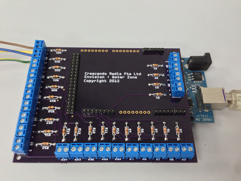
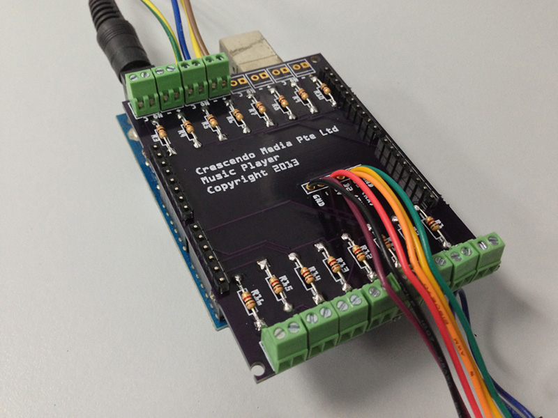
For my button shield which is a simple shield with 8 buttons and a VMusic2 header connector, I needed a total of 18 digital I/O pins. 16 of them are used for buttons with LEDs and each button uses a pair of I/O pin. The remaining 2 I/O pins are used for serial communication between Arduino and VMusic2.
-
Choose an Arduino board we’re going to use as a base. Depending on I/O and size requirements, there are a few boards to choose from: Arduino Uno, Arduino Mega and some others. Since my shield needs 18 I/O pins, Arduino Uno is a good choice.
-
Plan and sketch the shield layout on paper and prototype part of it on breadboard to make sure it works. Another thing to do at this stage is part and wiring arrangement. For button, I normally put the wiring in the order of +, -, NO and C. + and - for LEDs and NO and C for button or sensor. Of course, you are free to have your own convention.
-
Translate the sketch into schematic using PCB program such as Eagle or Fritzing. Since this is my first time using a PCB program before, I chose Fritzing. For the most part, it’s because the learning curve is gentler.
-
In the PCB program, select the board you have determined to use as a base template, add parts and establish connection on top of it. Try arranging the parts close to their respective pins if possible as this helps simplify for later routing.
-
Fortunately, Fritzing does the hard work for us with its auto-routing. Although the routing it produces might not be as aesthetically pleasing as when we do the routing manually. Once the routing completes, we might get a few warnings such as connection overlap or parts too close to each other. If that is the case, we will have to re-adjust parts placement and repeat the routing process again.
-
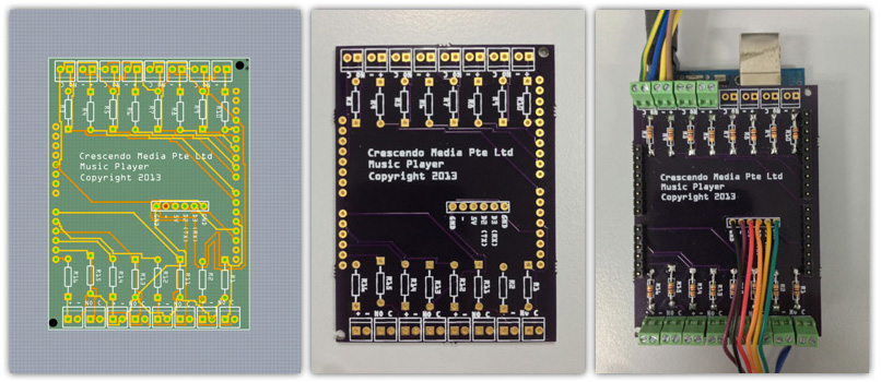
When routing completes successfully, cross-check the connection again to make sure everything is in place. I did this by going through each part to make sure they lead to to correct pins. We can print the etch-able design for another check or place the print on top of the real board for visualisation.
-
Once we are confident everything is done, the next step is to generate PCB Gerber file and send it for fabrication. There are a few shops out there offering fabrication service like Fritzing Fab and OSHPark. I used OSHPark and I personally recommend them as their pricing is quite cheap for small order, the printed board quality is great and the support is friendly (Thanks, Laen!). There is one thing to keep in mind though, OSHPark only allow order in the increment of 3 for 2 layer PCB, you can see their pricing table for detail. Another thing is for shipment, try choosing either UPS or Fedex if possible because from experience, my USPS package took a long time to arrive to Singapore.
-
To me, the exciting part is when I got to hold the boards on hand and put all parts unto the board. Yet it felt uncertain because the boards might turned out not working. So what I did first was to hook up the least amount of parts for it, write some test code and upload it to make sure the board stacking on top of Arduino really work before putting up the rest of the parts.